Photonic Systems Integration
Laboratory
Planar waveguide LED illuminator with controlled directionality and divergence


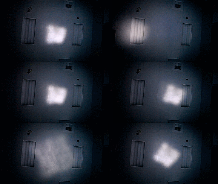
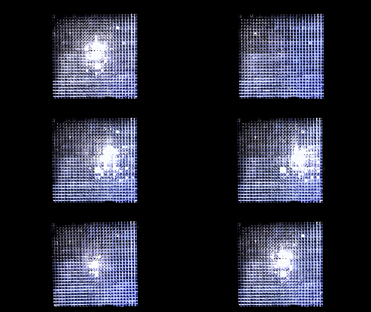
Adjusting the directionality and divergence of the prototype illuminator. The left video shows the light output (projected onto the lab ceiling), and the right video shows the corresponding view of the illuminator aperture (located on the lab floor).
Conventional illumination systems are typically designed to provide either directional or diffuse illumination (spot or flood lighting) using a fixed optical path through collimating or diffusing optics. In environments where the required type of illumination varies, light energy could be used more efficiently if the source could adapt to provide illumination consistent with the user’s immediate need. For example, in home or office lighting the user may want to switch between directional task lighting to illuminate a workspace and diffuse lighting to illuminate an entire room.
Our work demonstrates such a versatile illumination system. White light emitting diodes are coupled through a planar waveguide to periodically patterned extraction features at the focal plane of a two dimensional lenslet array. Adjusting the position of the lenslet array allows control over both the directionality and divergence of the emitted beam. An analytic design process is used to optimize the system geometry. Detailed modeling shows optimal designs can achieve high luminous emittance (1.3x10⁴ lux) over a 2x2 foot aperture with over 75% optical efficiency while simultaneously allowing beam steering over ±60° and divergence control from ±5° to fully hemispherical output. A 2x2 foot aperture proof-of-principle prototype system was fabricated and characterized to validate the design model.

Conceptual illustration of the planar illumination system. The components have been exploded for clarity.

Section of the array showing a collimated beam when the arrays are aligned (a), a redirected beam when the arrays are translated (b), and a diverging beam when the arrays are rotated (c).

Dialux modeling of a conventional 2x2 foot LED fixture and our optimized waveguide illuminator (modeled in Zemax). The waveguide system was simulated in three configurations: [diffuse] 1° rotation, [spot 1] (Δx, Δy) translation = (-3, 3) mm, and [spot 2] (Δx, Δy) translation = (5, 0) mm.

Proof-of-principle prototype. (a) System components: (i) waveguide, (ii) ball-bearing extraction feature, (iii) lenses, and (iv) PCB, LEDs, and CPC coupler; (b) assembled system (shown without cover); and (c) exploded CAD model.

Simulation (left column) and measurement (center column) of on-axis, off-axis, and diverged spots 3 meters from the aperture. The right column shows the corresponding view of the aperture from an angle.
JOURNAL PUBLICATIONS:
PRESENTATION SLIDES: